Introduction to radio interferometry
Radio interferometry is an advanced technique, developed by professional radio astronomers, that allows to use many smaller antennas instead of a too large one. In fact, when we think of a radio telescope, we imagine an instrument of enormous dimensions, equipped with a very large parabolic antenna that collects radio waves coming from space. By using many compact radio telescopes, radio interferometry improves results in radio astronomy research and allows the use of more affordable radio telescopes. For example, by using this technique the Event Horizon Telescope (an international collaboration of multiple radio telescopes from all over the world) recorded, in April 2019, the first radio map of a black hole inside the M87 galaxy, with an incredible resolution of 25 microarcseconds!
Radio interferometry: basics
When we look at a point source, such as a star, with a telescope, a point image will not form on the focal plane since the circular aperture of the instrument causes diffracted rays to generate a particular “pattern” on the focal plane, first explained by George Airy in 1835 with his “wave theory of light”: this pattern consists of concentric light regions alternating with dark ones. These rings, increasingly weaker as you move away from the center of the pattern, are the product of diffraction and have a peak in the central area, called “Airy disk”.
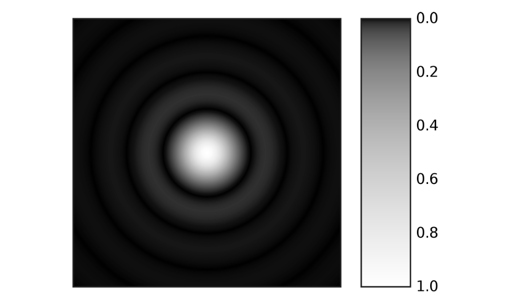
The optical resolving power of a telescope is related to the size of the Airy disk which depends on the wavelength λ of the observed radiation and the diameter D of the instrument. Using the approximation for small angles, Airy’s disc has an angular size given by the equation θ ≈1.22 λ/D: the larger the diameter of the instrument, the greater the theoretical resolution. If we now assume to observe a celestial object formed by 2 or more stars arranged very close to each other, Airy’s discs will overlap on the focal plane of the telescope, therefore it will be possible to “resolve” each of the stars only if the peaks the centers of each pattern won’t be added destructively, that is when their focal plane distance is no shorter than the radius of Airy’s disc (this rule known as Rayleigh’s condition).
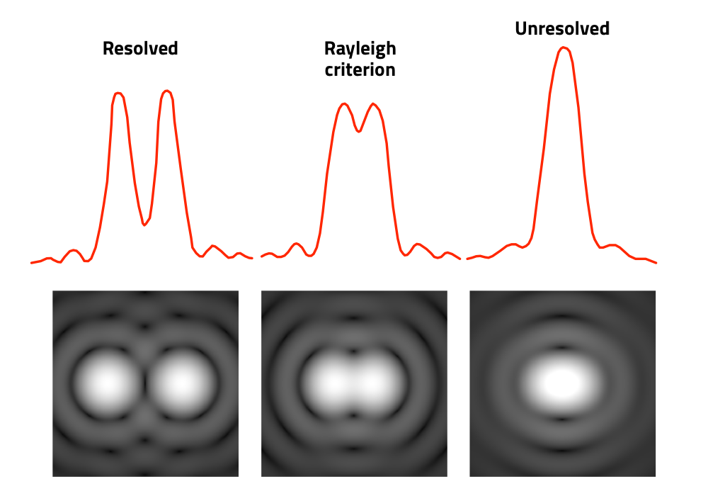
This applies not only to optical telescopes but also to radio telescopes which, due to the longer wavelength they record to “observe” the sky, have a much lower resolution capability than the optical ones, given the same diameter. For example, in order to match the resolution of Hubble Space Telescope (2.4 meters in diameter), ALMA, one of the most modern radio telescopes recording millimeter radio waves, would need a 5 km diameter parabolic antenna.
First interferometers
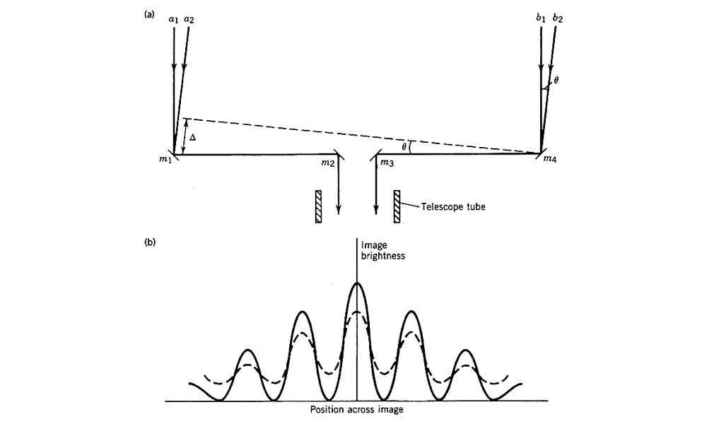
Michelson’s interferometer is based on the interference properties of light: a beam of electromagnetic waves coming from the same source (in the case of a radio telescope, from a celestial object) is divided into 2 parts on different paths and subsequently reconverted. If the 2 paths have different lengths or move through different materials, there is a phase shift in their optical path. We will obtain maximum light intensity when the angle θ formed by the direction of the star with respect to the optical axis of the instrument is such that the difference between the paths of the 2 beams is an integer number of wavelengths (with respect to the center of the passband). If the angular dimensions of the star are small compared to the space between 2 adjacent interference maxima, the image of the star will be crossed by a clear pattern of alternating dark and light bands, known as interference fringes. Conversely, if the angular dimensions of the star are comparable to the spacing between the maxima, the image will be the result of the superposition of a series of patterns along the star, where the maxima and the minima of the fringes do not coincide and the amplitude of the fringe will be attenuated, as shown in figure below (b). Thanks to this technique, in 1920 Albert Michelson and Francis Pease created the first “stellar interferometer” and by using it they measured that the diameter of the Betelgeuse star was equal to the Mars orbit.
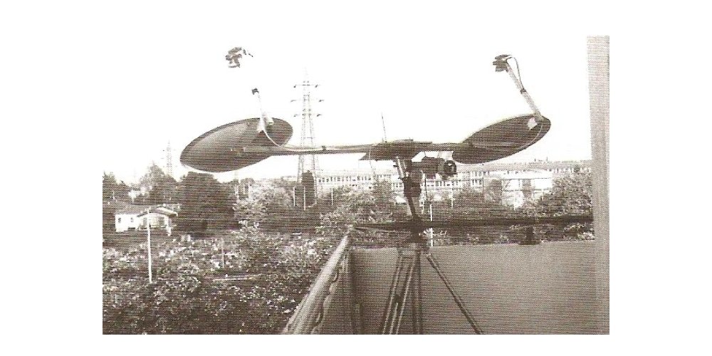
The first radio interferometer dates back to 1946 when it was used by Ryle and Vonberg for the study of radio emissions from space that a few years earlier had been first discovered by Jansky, Reber and others. This interferometer was formed by an “array” (a group) of 2 dipole antennas operating at 175 MHz frequency and having a baseline D (distance between the antennas) varying between 17 and 240 meters.
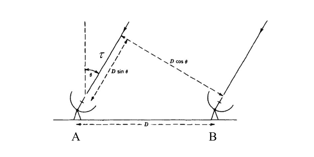
It was a so-called “transit interferometer”, a diffused type in the 50s and 60s of the last century, that needed antennas to be pointed to the local meridian, at a certain elevation, and wait for the earth’s rotation to move the object along the Right Ascension. If θ is the zenithal angle of the object to be observed and is different from zero, the electromagnetic waves will reach antenna B first (see figure above) and subsequently antenna A with a delay τ=(D/c) sinθ, where c is the speed of light. The detector of the receiver, integrated over time, will generate a response proportional to the square sum of the voltages of the 2 signals similar to the trace in picture below.

Modern radio interferometry
The countless technological advances of recent years have led to a large use of interferometry in radio astronomy. Just think of the large networks of professional radio telescopes that form the VLBI, Very Long Baseline Interferometry, which has been operating since the late 1970s by connecting several instruments distributed in several parts of the world, with the aim of creating a single large instrument with an equivalent diameter of thousands of kilometers. Among the most sensitive and performing networks in the world there is the EVN, Europe VLBI Network, which uses the largest European radio telescopes for periods of a few weeks a year.
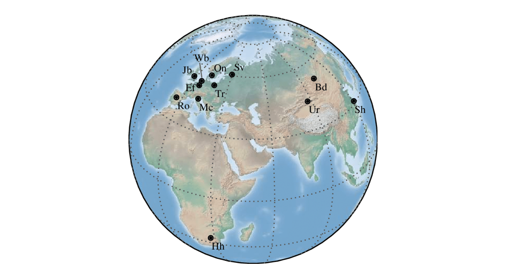
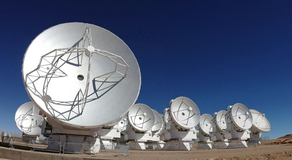
Among the most famous networks we also remember the VLBA, Very Long Baseline Array, which uses 25 radio telescopes located along the American continent; ALMA, an array of antennas that rises on the Chilean plateau at 5000 meters above sea level and that since 2013 observes the sky in wavelengths from 0.3 to 9.6 mm; LOFAR, an interferometer managed by ASTRON in the Netherlands capable of mapping the universe at frequencies between 10 and 240 MHz; SKA, the Square Kilometer Array, an ambitious project currently under construction that will see the creation of 2 arrays ensuring constant coverage of frequencies from 50 MHz to 14 GHz.
Radio interferometry with small instruments?
Although some experiments of amateur radio interferometry date back to the 80s of the last century, it was with the advent of the Sat TV systems at the end of the last century that we a progressive increase in amateur experiments, however always by few electronics experts.
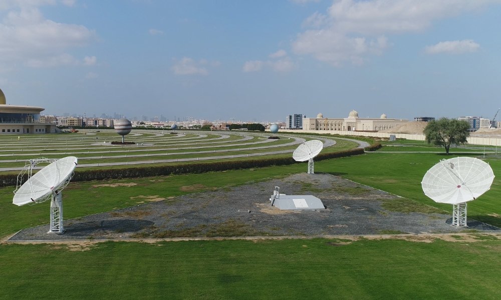
The challenge of creating a radio interferometer that was within the reach of research groups, schools and universities was taken by PrimaLuceLab that, after the development of the SPIDER radio telescopes for radio astronomy (with parabolic antennas up to 5 meters in diameter and receivers to capture the n neutral hydrogen wavelength at 21 cm) has now presented the project of its radio interferometer with the installation of the first array of 3 radio telescopes, 5 meter diameter each, at the Sharjah Academy for Astronomy, Space Sciences & Technology near Dubai (UAE).
The difficulties in the realization of an interferometer project are many: first of all the antennas that compose the array must have very high mechanical precision, with a mount for radio sources pointing and tracking ff the large antennas equipped with a precision similar to the one of an optical telescope. SPIDER radio telescopes are in fact equipped with ultra-low backlash alt-az mounts and with encoders capable of reading few arc seconds errors. They are also equipped with an specially designed feed for 21cm wavelength, with double polarization, connected to very low noise LNAs that amplify the signal before it reaches the receiver. For the operation of the interferometer, PrimaLuceLab is developing a device that transforms the radio frequency output from the LNA into an optical signal over fiber, even at distances in kilometers. This eliminates the normal coaxial cables and therefore the losses in the signal between antennas and receivers.
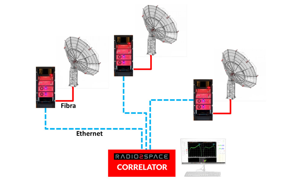
In the control room, on the other end of the optical fiber, the signal will be transformed in the RF band and connected to the receiver (one for each antenna). To maintain adequate time consistency, a synchronization device will also be developed for the timing of radio telescopes and for the acquisition system. Then, signal will be digitized by means of an extremely performing backend and which will save the data on disk for subsequent processing. Finally, signals from each antenna will be sent to the digital correlator that, based on the Fourier transform, will perform the calculations necessary for the signal correlation and will output the visibility functions for each baseline of the antennas array.
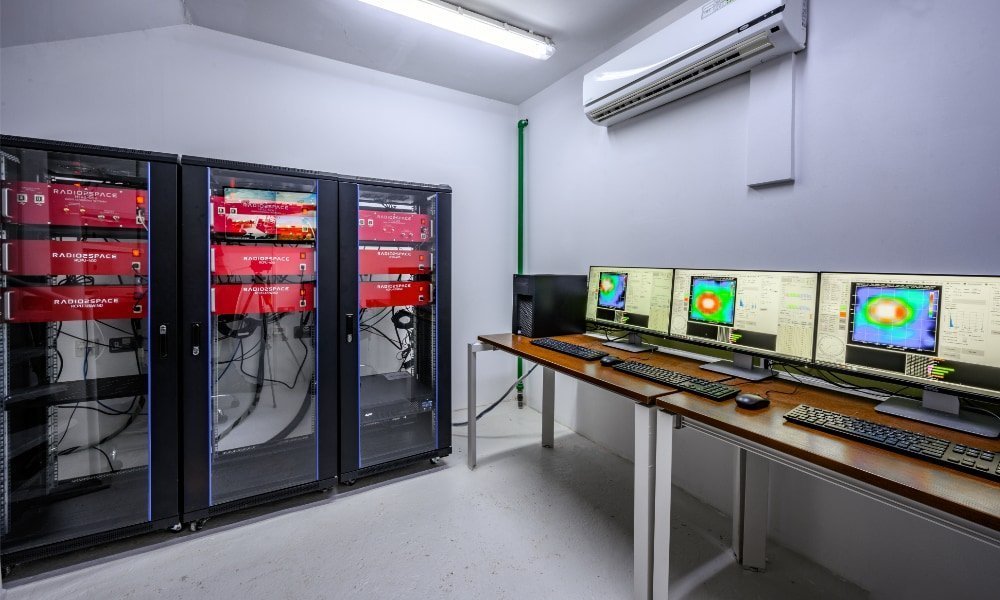
Thanks to the radio interferometry technique, we are developing an affordable interferometer system to simultaneously use many radio telescopes and obtain high resolution radio maps of radio sources in the Universe. The system will be configurable with a variable number of antennas and it will also allow the user to increase their performance by installing more antennas in a later moment. Thanks to this system, universities, scientific museums, planetariums, research institutes but also groups of amateurs will have at their disposal a scientific instrument, ready to use but very powerful, that up to yesterday was available only to professional researchers.
Salvatore Pluchino
Filippo Bradaschia
